32 Harley Crescent Condell Park NSW, 2200 Australia
How to Prepare a CAD Drawing for Laser Cutting
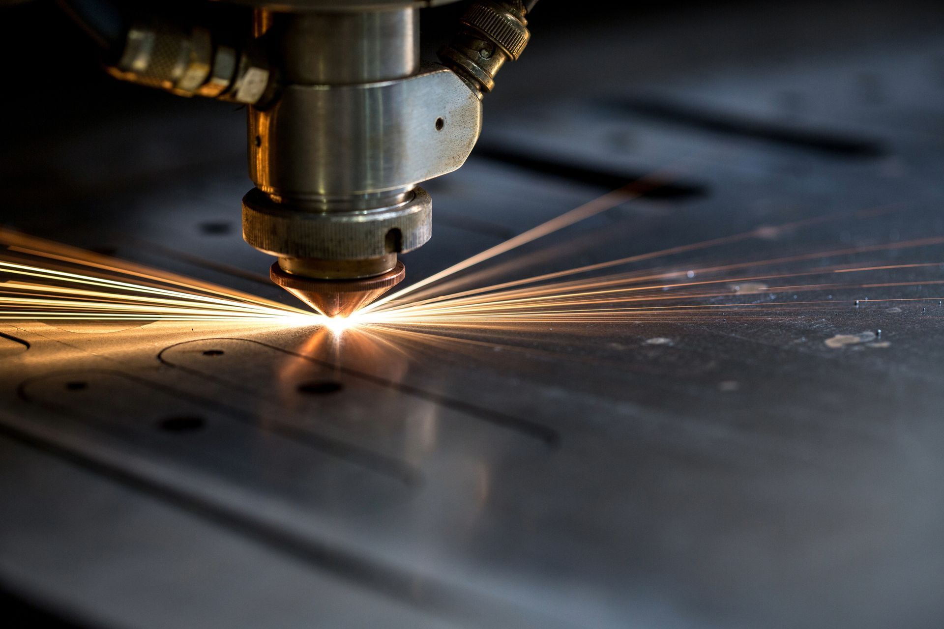
Getting a CAD drawing ready for laser cutting is one of those steps that looks straightforward on the surface but carries a surprising number of traps. A file that looks perfectly clean on screen can produce burnt edges, missed cuts, or misaligned parts once it hits the laser cutting machine.
Whether you're working with mild steel, stainless steel, aluminium, brass, or copper, and whether you send design files to a service or run your own laser, the preparation process follows a consistent set of rules.
In this blog post, we walk you through everything from acceptable file formats to the final pre-submission checklist, so your next project moves from drawing to finished laser cut parts without unnecessary rework.
Shift Your Thinking from 3D to 2D
If you come from a mechanical or product design background, the first mental adjustment is moving away from 3D modelling and into 2D, vector-based, path-oriented design. Laser cutters operate on flat sheets of material, and the machine reads paths, not surfaces, volumes, or solids.
Your drawing must be strictly 2D. When exporting from 3D CAD software, many programs carry Z-values into the output file. Even a Z-value of zero can confuse laser cutting software, causing it to misinterpret geometry or reject the design files entirely. Before exporting, confirm that all objects sit on a single flat plane with no depth information attached.
Choosing the Right File Format
File format matters more in laser cutting than most people expect. Vector files or formats are the standard because they preserve outlines, scale without quality loss, and allow different line types and colours to represent different machine actions. These are the acceptable file formats most laser cutting services work with.
The most common file formats accepted by laser cutters include:
- DXF — The most widely used format in the industry and a popular choice for precision work. DXF files preserve measurements, layers, and distances accurately. When exporting, avoid duplicate polylines and check that your unit settings match what your cutting service expects (millimetres is standard in Australia). Software like AutoCAD exports DXF natively, making it straightforward for users coming from a traditional CAD workflow.
- SVG — Popular for web-based design tools and well-supported by software like Inkscape and Adobe Illustrator. Free SVG files are widely available online and can be downloaded and modified to suit your project.
- AI — Adobe Illustrator's native format, accepted by many services and compatible with most professional laser cutting workflows.
- PDF formats — Useful as a preview file and sometimes accepted as a cutting file, though it's best sent alongside a dedicated vector format.
- CDR and DWG — Less universal but accepted by some services depending on their software setup.
- EPS format — Less common but still accepted by many services; useful when working across different design software platforms.
Vector file formats such as DXF, EPS, and SVG are preferred because they preserve outlines and support various formats of line types and colours across a diverse range of materials and applications.
For a deeper look at which format performs best in different scenarios, our post on the best file type for laser cutting covers the trade-offs in detail.
Design Software Options
Choosing the right tools for laser cutting comes down to project scale and budget.
- Adobe Illustrator is a professional-grade vector tool. It exports AI files, SVG, PDF, and DXF, and has plugins available that convert vector paths to G code for direct machine control.
- Inkscape is a free, open-source option comparable to Adobe Illustrator, keeping cost low for smaller operations. It exports to SVG and DXF and is a solid pick for anyone who is a new laser user or running a small business.
- LightBurn is designed specifically for laser cutters and doubles as a layout tool, making it practical for anyone running their own machine.
If you're generating new designs from scratch, any of these tools will let you build project files and export in formats compatible with most cutting services.
Free Laser Cut Files and Design Templates
Not every project needs to start from a blank canvas. There's a vast collection of free laser cut files and free laser files available online across a wide range of categories — from home decor and wall art to mechanical assemblies and signage.
Where to Find Free Design Files
Sites like Vecteezy, Thingiverse, and Free DXF offer an extensive collection of free design files across DXF, SVG, and PDF. Many of these platforms allow you to access free files without registration, and there are plenty of free options that don't require an account at all. A quick browse through any of these sites will turn up images, patterns, and vector shapes ready to be downloaded directly from the website.
When working with downloaded files, always check:
- Whether the design is licensed for personal use, commercial use, or both
- The native format of the file (DXF and SVG are most compatible with laser cutters)
- Whether you need to modify the design to fit your sheet size or material thickness
Some sites focus on free laser cut files specifically for hobbyists, while others offer broader free design files spanning multiple industries.
Using and Adapting Laser Cutting Templates
Laser cutting templates and design templates are a useful starting point, but most templates need minor adjustments before they're ready to cut. Always confirm that downloaded files are proper vector files, not flattened images or embedded rasters. Check that they are at 1:1 scale, all paths are closed, and any scanned or traced elements have been converted to clean vector paths.
Setting Up Your Document Correctly
Work at 1:1 Scale
Design at the exact size the final part should be. Scaling files up or down during export introduces rounding errors, and scaling at the machine level creates kerf compensation issues. Set your canvas or drawing space to the actual sheet dimensions and place your parts within it.
Keep Everything Flat and Clean
Remove any construction lines, reference geometry, or hidden layers that aren't meant to be cut or engraved. A clean file reduces the risk of the laser cutting machine acting on geometry you didn't intend it to process. Keeping design files tidy at this stage saves time downstream.
Close All Shapes
Open paths are one of the most common causes of incomplete cuts. If a shape has even a tiny gap in its outline, the laser cutters will stop at that point and leave an uncut section. Before exporting, use your software's "find open paths" or "check geometry" function to catch any unclosed contours. Every shape that needs to be cut out must form a fully closed loop.
Colour Coding and Layers
Organising your file by colour and layer is how you communicate different instructions to the laser. Standard colour conventions used across the industry are:
- Red — Through-cuts (full depth cuts that separate parts from the sheet)
- Blue — Scoring or etching lines (partial depth cuts)
Keeping these on separate layers (one for cuts, one for scoring) gives the operator clear control over the order and power settings applied to each action. Most laser cutting software reads layer names or colours and assigns different parameters to each.
Understanding and Accounting for Kerf
Kerf is the width of material removed by the laser beam as it cuts. Depending on the material and machine settings, kerf typically falls between 0.1mm and 0.5mm. For decorative parts or rough cuts, this rarely matters. For parts that need to fit together — interlocking joints, press-fit assemblies, or precision brackets — ignoring kerf will leave you with parts that are either too loose or too tight.
To compensate, offset cutting lines inward for internal cuts (holes, slots) and outward for external cuts (profiles, outlines). The offset distance should equal half the kerf width. Your CAD or vector software will have a path offset or contour tool for this.
Laser cutting with higher-power machines tends to produce a wider kerf, so always confirm the expected kerf width with your service before finalising tight tolerances. Alongside kerf, maintain a minimum gap of at least 1 to 2mm between adjacent cut lines on the same sheet. Cutting too close to a previous cut leaves the material fragile or causes heat from one pass to affect the next.
Duplicate Lines and Other Geometry Traps
Duplicate lines are invisible in most design views but cause real problems at the machine. When two identical paths sit on top of each other, the laser cuts the same line twice, which leads to excessive charring, a wider-than-expected kerf, or in worst cases, a fire risk. This often happens when importing from CAD software that mirrors geometry or when copy-pasting without realising existing lines are already there.
Use your software's "delete duplicate" or "clean up" function before exporting, and check the file visually at high zoom to spot any overlapping geometry. This is especially important when working with laser cutters that run unattended. Catching duplicate lines before submission prevents costly material waste.
Minimum Feature Sizes
Small details add character to a design but can disappear entirely in the cut if they're too fine. As a rule, any feature — a thin bridge, a narrow tab, or a small cut-out — should have a minimum size equal to at least 50% of the material thickness. On 3mm acrylic, that means no feature narrower than 1.5mm. On thicker materials, this threshold increases accordingly.
Fine bridging can also burn away if surrounded by other cuts, so space your detail work thoughtfully and consider whether a feature that looks clear on screen will survive the laser cutting process.
Text and Fonts
Never submit a file with live text. If your design includes lettering or numbers, convert all text to paths, outlines, or curves before exporting. Failing to do so means the receiving computer will substitute whatever font it has installed, which may change your spacing, letter shapes, and overall layout.
Converting to outlines locks the geometry in place and makes the design files self-contained. This also applies to any hand drawn lettering that has been traced or digitised. Make sure all strokes are converted to closed paths before submission.
Spacing Between Parts
When nesting multiple parts on a single sheet, maintain a minimum spacing of 3mm between objects. This prevents laser cutting paths from interfering with each other and gives enough material between parts to avoid weakening the sheet mid-run. If parts shift slightly during cutting, adequate spacing also prevents the laser from accidentally re-cutting an adjacent edge.
Final Checklist Before Submitting
Before sending your file to a cutting service, run through these points:
- File format accepted by your cutting service — DXF, SVG, AI, or PDF
- All geometry is strictly 2D with no Z-values
- All shapes are completely closed
- No duplicate or overlapping lines
- Correct colour coding and layers for cut and score
- Design is at 1:1 scale in millimetres
- Kerf compensation applied where tight fits are required
- Minimum 3mm spacing between parts on the sheet
- All text converted to outlines or paths
- A PDF preview included alongside the vector file
- Material type and thickness noted in your submission
- Downloaded files checked for correct scale and open paths before submission
Working with a Laser Cutting Service
A well-prepared file saves time, reduces back-and-forth, and gets your parts into production faster. If you're unsure whether your file meets the requirements, most services will do a quick file check before quoting.
As experienced laser cutting Sydney specialists, we work with a wide range of materials and file types and can advise on the best setup for your specific project. Getting the CAD preparation right from the start is the most efficient way to move from design to finished part without unnecessary rework.
RECENT POSTS
Prototyping lets you test functionality and refine designs before full production. Learn why laser cutting is the right tool for the job.

The best laser cutting company blends decades of know-how, technology, and outstanding service. Find out why Hygrade raises the bar.
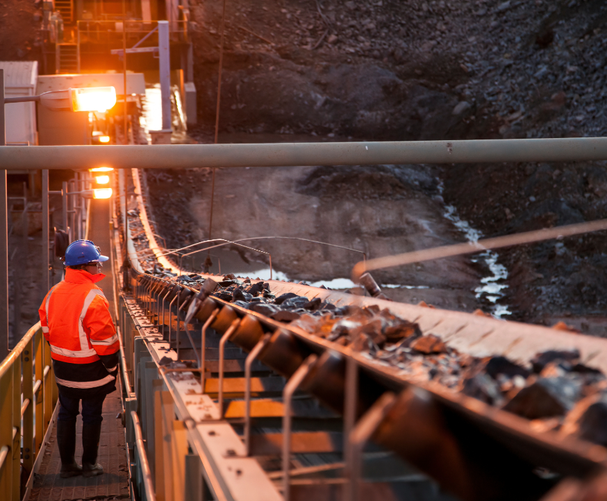
Find out how laser cutting supports key industries across regional NSW—from mining and agriculture to transport and infrastructure.

Mining equipment failures can be costly. Pipe and tube laser cutting delivers high-strength replacement parts fast, reducing downtime and keeping operations running.

Stronger welds, seamless connections, and high-precision cuts — tube laser cutting ensures construction components meet the highest durability and safety standards.
Prototyping lets you test functionality and refine designs before full production. Learn why laser cutting is the right tool for the job.
The best laser cutting company blends decades of know-how, technology, and outstanding service. Find out why Hygrade raises the bar.
Find out how laser cutting supports key industries across regional NSW—from mining and agriculture to transport and infrastructure.
Mining equipment failures can be costly. Pipe and tube laser cutting delivers high-strength replacement parts fast, reducing downtime and keeping operations running.
Stronger welds, seamless connections, and high-precision cuts — tube laser cutting ensures construction components meet the highest durability and safety standards.

Automotive manufacturers rely on tube laser cutting for precision, cost efficiency, and high-performance components. Learn how this technology is driving innovation.

Tube cutting enhances agricultural equipment durability, efficiency, and performance. See how custom fabrication supports farming and manufacturing needs.
From the history of lasers to the advancements that enabled them to produce precise, clean cuts, explore the remarkable journey of lasers and their transformative impact on modern technology.
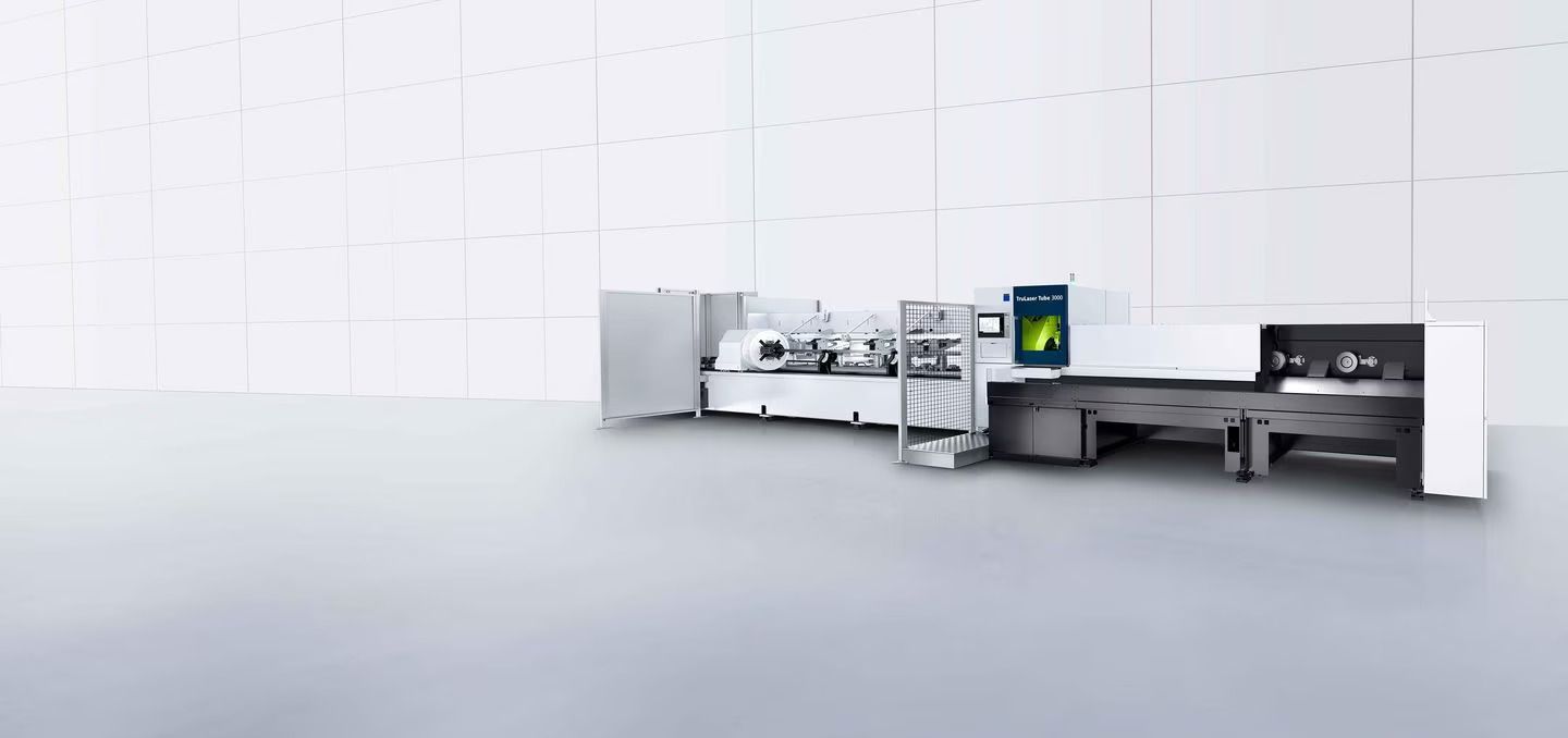
Hygrade Laser Profiling is upgrading to the TruLaser Tube 3000 Fibre for superior cutting results. This advanced machine enhances efficiency and precision for all your laser profiling needs.